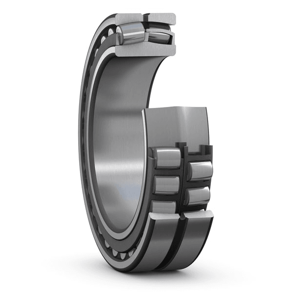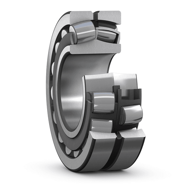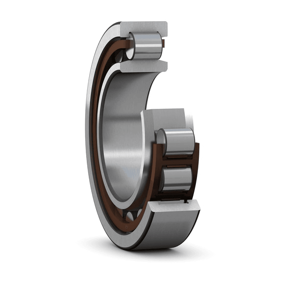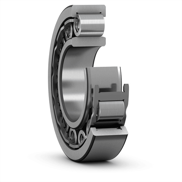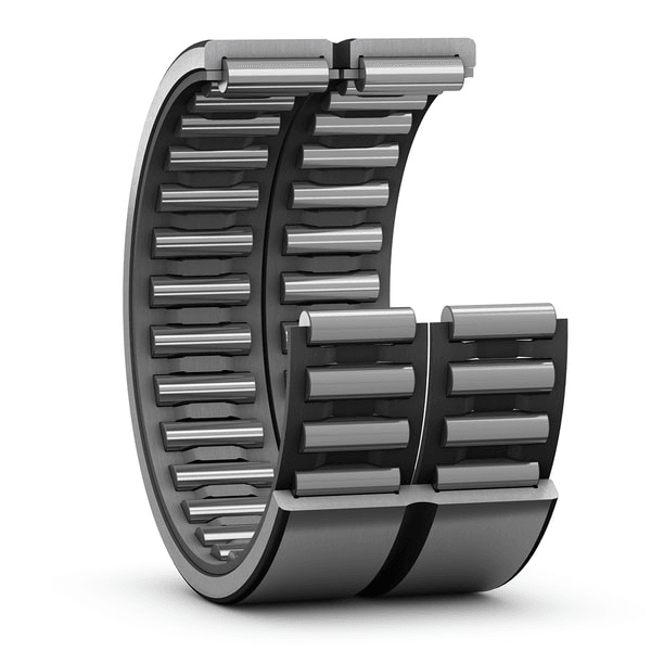


Description
| Bore type | Cylindrical |

Dimensions
| d | 600 mm | Bore diameter |
|---|---|---|
| tΔdmp | -0.05 – 0.0 mm | Deviation limits of mid-range bore diameter |
| D | 870 mm | Outside diameter |
| tΔDmp | -0.1 – 0.0 mm | Deviation limits of mid-range outside diameter |
| B | 272 mm | Width |
| tΔBs | -0.5 – 0.0 mm | Deviation limits of ring width |
| d2 | ≈ 682 mm | Shoulder diameter of inner ring |
| D1 | ≈ 784 mm | Shoulder/recess diameter of outer ring |
| b | 46.1 mm | Width of lubrication groove |
| K | 15 mm | Diameter of lubrication hole |
| r1,2 | min. 6 mm | Chamfer dimension |
| Normal | ISO tolerance class for dimensions |

Abutment dimensions
| da | min. 623 mm | Diameter of shaft abutment |
|---|---|---|
| Da | max. 847 mm | Diameter of housing abutment |
| ra | max. 5 mm | Radius of fillet |
Calculation data
| NR performance class | NR Explorer | |
| Basic dynamic load rating | C | 8 502 kN |
| Basic static load rating | C0 | 16 300 kN |
| Fatigue load limit | Pu | 1 100 kN |
| Reference speed | 20 r/min | |
| Limiting speed | 45 r/min | |
| Limiting value | e | 0.3 |
| Calculation factor | Y1 | 2.3 |
| Calculation factor | Y2 | 3.4 |
| Calculation factor | Y0 | 2.2 |
Tolerances of run-out
| Range of section height at inner ring of assembled bearing | tKia | 70 µm |
|---|---|---|
| Range of section height at outer ring of assembled bearing | tKea | 140 µm |
| ISO tolerance class for geoal tolerances | Normal |
Radial internal clearance
| Minimum initial clearance | 310 µm |
| Maximum initial clearance | 480 µm |
Tolerances and clearances
General bearing specifications
- Tolerances: Normal, P6, P5,
tapered bore 1:12, tapered bore 1:30 - Radial internal clearance: cylindrical bore, tapered bore
Bearing interfaces
- Seat tolerances for standard conditions
- Tolerances and resultant fit
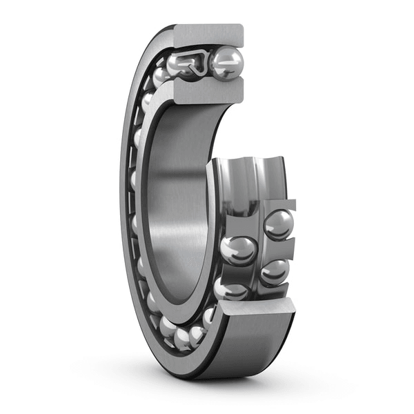
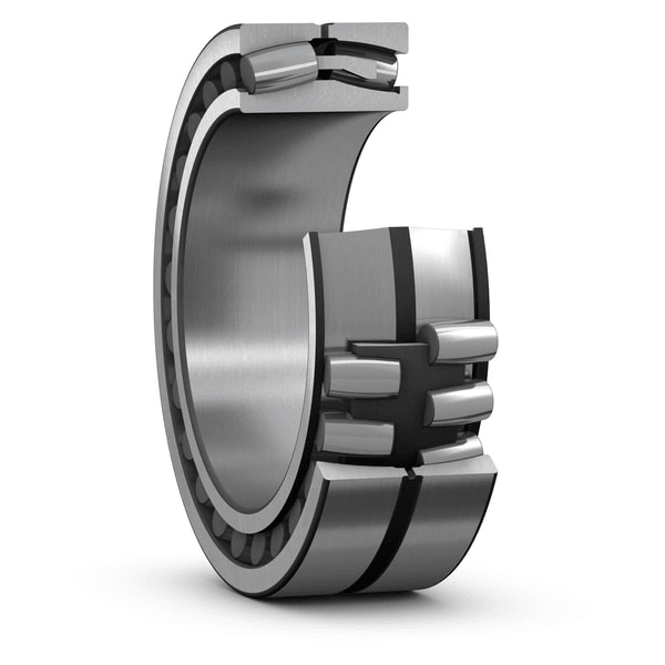
Spherical roller bearing for wind turbine main shafts are optimized to handle the varying direction and high thrust loads of wind energy applications, allowing to perform more reliably under typical operating conditions. A modified inner geometry with super-finished functional surfaces makes this possible. Using a one-piece roller-guided cast-iron cage and an enlarged lubrication groove increases robustness.
- Improved performance under wind operating conditions
- Accommodate misalignment
- Up to twice the fatigue life
- Increased robustness for both radial and axial load conditions
- Improved lubrication